
How it works
A CNC wood router works almost the same as any other CNC machine. A CNC machine or a Computer Numerically Controlled system which uses computer software and CNC controller electronics to drive a mechanical system. Using this setup, it is possible to achieve far better accuracy and precision than a human operator.
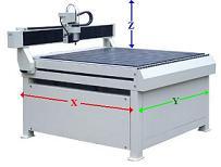
A traditional CNC router can move and cut in three directions which are usually referred to at the X, Y, and Z directions. The X-axis is usually the longest of the three running front to back. The Y-axis runs from left to right while the Z-axis runs up and down. Below you can see each axis labeled respectively.
The Components
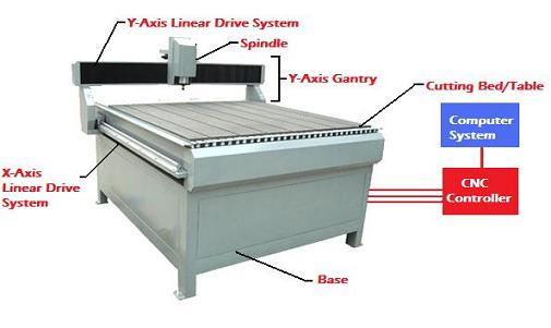
Lets identify the major components of these machines and see how they come together to make it all work. Below you can see a picture labeling the major components on a generic CNC wood router. There are many other components and additions available but most all routers have these components in common.
The CNC Controller and Computer System
The CNC controller and computer system work together as the brain for these machines, telling the motors and drive system which direction to move and how far. Of course the computer must be given a design.
Most designs start in a digital format such as a dxf drawing or some other similar format. The user would then use a CAM software package along with the CNC controller software provided. These types of software convert a 3D or 2D digital image into a tool path code such as G-code.
The computer then converts these commands into a digital signal which it relays to the CNC controller which converts the digital signal to varying voltages and currents that control the mechanical drive systems.
Most of this is far more than anyone operating a CNC wood router would need to know. It is usually plug and play. The user interface varies depending on the type or manufacturer, but the overall process is the same. You begin with a digital design and then use additional software to make tool paths for the machine to follow.
The Spindle
The spindle is the part of the machine doing the cutting. Think of it as the actual router, such as a standard wood router. The
router spindle
is classified by its power rating, horse power in English units and Watts in SI units.
The spindle works bye rotating a cutting tool, such as router bits, at varying speeds. A typical spindle designed to cut wood plastics and other soft materials usually have a range of 8000 to 30,000 revolutions per minute. Spindles designed to cut metals operate between 2000 and 10,000 RPMs.
Most CNC wood routers are capable of cutting metals as well. However, it is usually limited to non ferrous metals such as aluminum. When cutting metals or carbon based composites at high spindle speeds, a coolant system that cools the material being cut and the tool itself is usually necessary.
Some spindles are controlled via the CNC controller which regulates the RPM based on material and the feed rate of the machine. There are other options that may be installed as well, some of which include an automatic tool changer, tool sensor, and touch probe.
The Cutting Bed
The cutting bed is where all the action happens. The cutting bed may come in several different types but the function remains the same. The cutting bed is designed to support and secure the piece of material being cut.
There are several different designs that do this effectively. Some of the most common cutting bed designs cutting bed designs are the T-slot, pictured above, and the vacuum table. The T-slot style table works well for most any part as it uses bolts and clamps to secure the piece to the bed.
The vacuum table is found on many high end models and works well for companies cutting the same design several times a day. However, it is limited to relatively flat pieces such as wood and sheet material. The T-slot is more versatile in that is can hold virtually any piece but lacks in efficiency and speed of setup.
There are many other types available, some are a hybrid mix employing both a T-slot and the vacuum design. However, these are the two primary types of cutting beds.
The Linear Drive Systems
Each axis employs a linear drive system that moves the spindles in that axis. The
CNC linear drive system
includes a motor, a linear bearing system, and some sort of lead screw assembly.